Hydroboost Installation on a C3 Corvette
Hydroboost braking systems have been around for a long time. They have
been used on many GM truck models and have been used on race cars for years.
How does a hydroboost system work? Before I answer that question let me
explain how the conventional power brake systems work. Most power brake
systems employ a vacuum booster to provide pedal assistance when braking.
That large drum attached to your brake cylinder in your engine compartment uses
vacuum produced by your engine to help push the plunger in the brake cylinder
when you apply pressure on the pedal.
A hydroboost system uses hydraulic pressure to assist in pushing the plunger in
the brake cylinder when you step on the pedal. The hydroboost unit simply
replaces the vacuum booster and fits between the firewall and the brake master
cylinder. Most hydroboost systems piggy-back on the power steering system
for the hydraulic pressure.
What are the advantages to the hydroboost system? The most noticeable
difference is in the braking response and reduced pedal effort. A typical
vacuum system depends on your engine for the vacuum source. Once engines
are modified, they often do not produce sufficient vacuum to provide the assist
necessary and therefore, stopping your car requires more pedal effort on the
part of the driver. The hydroboost system is much smaller and frees up
space in the engine compartment for things like deeper valve pan covers, etc.
Hydroboost kits are available from several sources for the C3 Corvette. Most of these kits use a Bendix unit and come with all the hoses and fittings for
the install. These kits require a 1977 or later master cylinder.
Manual brake C3 cars can be converted to hydroboost but require some holes to be
drilled in the firewall.
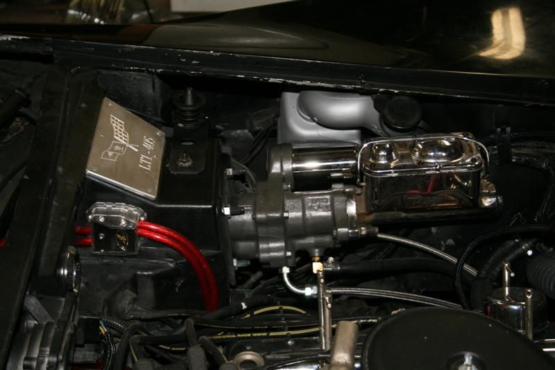
A typical Hydroboost Install in a C3 Corvette
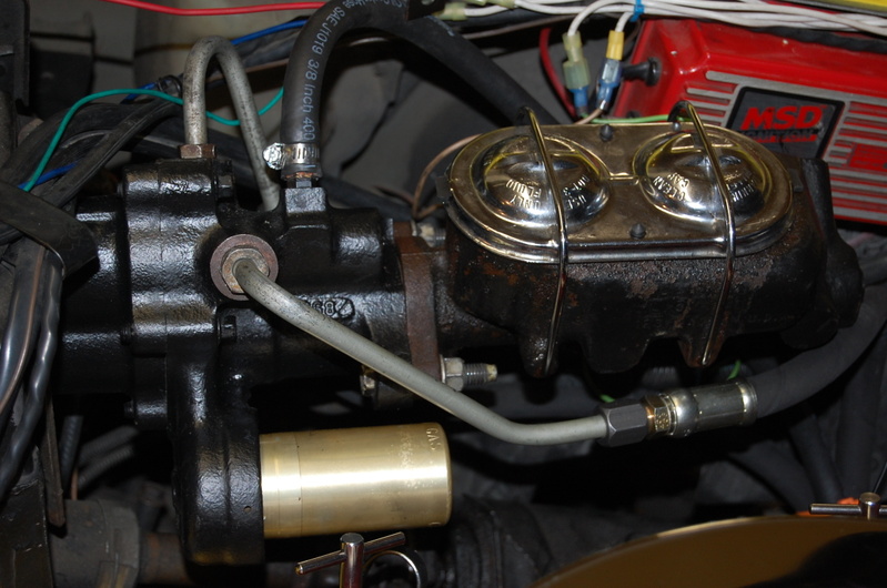
Another typical Hydroboost Install with a 180 degree
Rotation in a C3 Corvette
The actual install is quite straight forward. The first thing you will
want to do is to remove the old vacuum booster. This is probably the most
time consuming and frustrating step. The booster has four studs going
through the firewall and pedal bracket. The nuts on these studs must come
off. I suggest that you remove the driver seat unless you have a
chiropractor on call. You will need a deep socket, some extensions, a
universal and lots of patience. You also need to remove the clip and
clevis pin that connects the brake booster to the brake pedal.
On the firewall side, remove the two nuts securing the master cylinder to the
booster and pull the cylinder forward. It is not necessary to disconnect
the hydraulic brake lines as there is sufficient length in the lines in order to
pull the cylinder forward far enough to clear the booster for removal.
Disconnect the vacuum line from the booster and pull the booster free from the
firewall.
Before you start the install you should disconnect the high pressure line from
the power steering pump and let the fluid drain. The high pressure line is
the one which has the fitting screwed into the pump. You can also
disconnect this line from the steering control valve or in the case where you
have a Steeroids unit, disconnect the line from the rack. You can remove
this hose as you no longer need it. (Note: If you do have a Steeroids unit
you will need a high pressure hose with Aeroquip 18mm fittings on both ends as
the hydroboost and rack use the same connector.) While the power steering
fluid is draining you can now return to the install.
If your new hydroboost unit does not have a clevis on the plunger rod, you need
to remove the one from the old booster and install it on the new unit.
Install at the same position on the rod as it was on the old booster. You
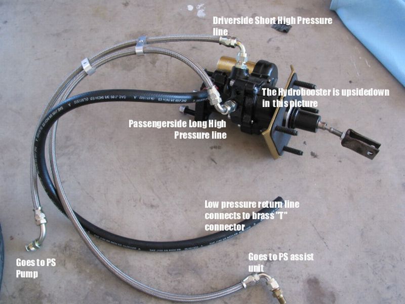
can now install the hoses on the hydroboost. There will be three of them.
Since they all have different fittings you cannot mix them up. The hoses
will all be on the bottom when the unit is installed. You are now ready to
push the unit through the firewall. Before you do that, make sure the
clevis is lined up with the brake pedal. Unless you have someone helping
you, this may take a couple of attempts. Once the unit is pushed through,
you can now put the four nuts back on and tighten the unit in place.
(Note: I highly recommend that you reverse the studs so that they come out through the
firewall into the unit with nuts on the firewall side. This makes it
easier for removal should that ever be the case.) You can now put the
clevis pin through the pedal and secure the clip. Put the seat back in and
take a break.
Push the master cylinder back over the studs of the hydroboost unit and secure
with the two nuts. You are now finished with the top part of the install.
Route the hoses down to the power steering pump and control valve (or rack).
Make sure to route the hoses away from the exhaust and any suspension components.
There is a brass tee fitting in your kit that needs to be installed in the
return line going from the pump to the control valve (or rack). Cut your
existing return line about five inches away from the pump fitting, slide clamps
over each side of the cut ends and install the tee in the line. Slide a
clamp over the new return line from the hydroboost and shove the hose on the
tee. Tighten the three clamps. Install the high pressure lines on
both the pump and the control valve (or rack).
You are now ready to add power steering fluid to the pump. I would suggest
that you disconnect your ignition temporarily so that you can turn your engine
over without it starting. That way you can keep adding fluid until the
system is pretty well filled. Connect your ignition and start the engine.
Check for any leaks. You might want to cut your wheels back and forth a
few times to help bleed the air out of the system. Check the fluid level
in the pump and top up if necessary. If you notice lots of air bubbles in
the pump, allow the car to sit for 30 minutes. You are now ready to test
the brakes. Make sure you have a hard pedal before you start up.
Once you start the engine, press the pedal a few times to make sure you indeed
have brakes. You may hear a hissing sign coming from the hydroboost.
This is normal until all of the air gets out of the system.
You are now ready for a test drive. I think you will be pleasantly
surprised. It may take up to 500 miles of driving before the system is
working at the optimum.
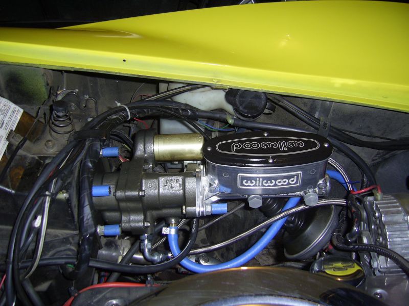
If you are looking for the correct Wilwood master cylinder (1.12" bore)
for this setup you need a 260-8556P Wilwood master.
If you are interested in more information about hydroboost for your C3 or are
interested in obtaining a kit, contact
Hydratech Braking Systems. They are extremely knowledgeable about this specific application.
Here is a picture of my setup and it works superb.
Hydroboost Setup on a 1977 C3 Corvette