Tips for Working on your C3 Corvette
Front Bumper Cover Replacement: Urethane to Flexible
Fiberglass
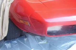
Due to age and
temperature change I found it necessary to replace the urethane bumper
cover this spring. This old one cracks just looking at it.
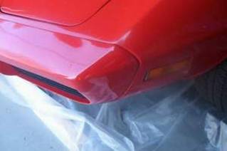
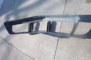
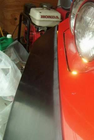
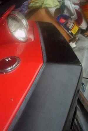
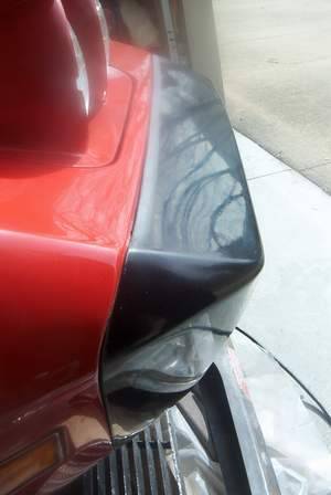
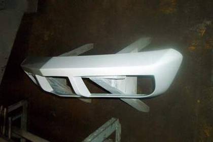
The pictures above show the fit on the sides of the
urethane cover.
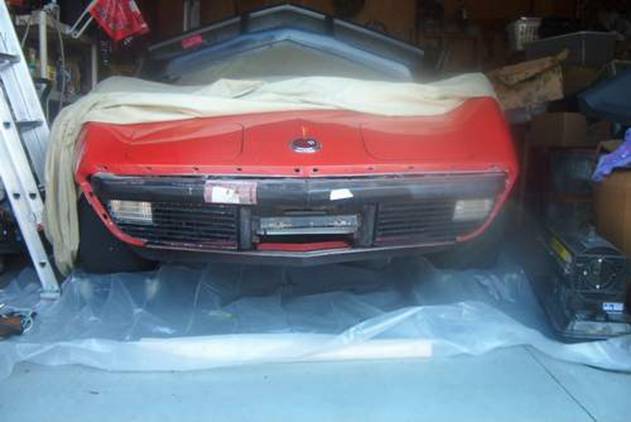
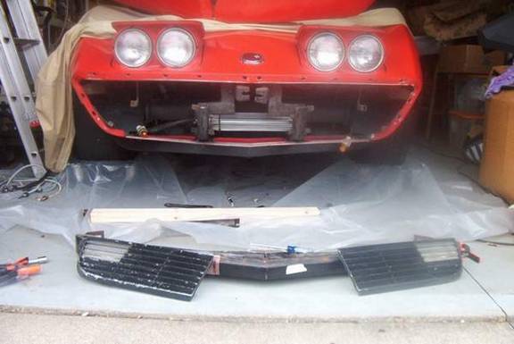
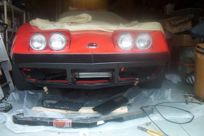
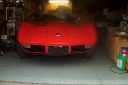
The picture
below shows the cover removed without removing the grilles or lower
valance. Notice the beam still has the shipping label from where it had
been replaced in the past.
With
the headlights in the up position and the turn signal sockets unhooked
from the grilles, I used a �� drive ratchet with a 3/8� socket to remove
the bumper cover. I reached up through the openings in the lower valance
panel to get to the fourteen nuts. The six bolts that attached the
bottom of the cover to the lower valance panel were removed with a 7/16�
socket.
Four bolts
hold the beam in place, one on each end and two in the center. Four
Philips head screws hold each grille on. I removed them to make it
easier for me to fit the
bumper to the
car before painting it.
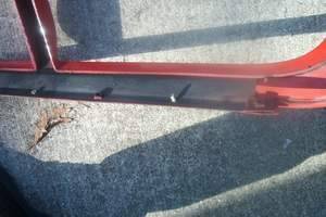
There is a metal brace with six nuts welded to it attached to the lower bumper cover. The brace is attached with four aluminum rivets. The top and side braces have studs welded to them and are held to the cover with spring clips over the studs.
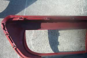
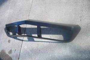
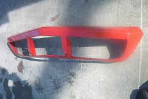
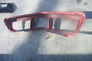
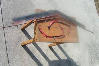
Here is a picture of the new bumper cover and the old one off the car. Note: the holes are not in the fiberglass cover yet. There are dimples in the area where they need to be. There is a small label on the inside of the cover that say�s it was made by Toledo Pro Fiberglass Ltd.
The fiberglass part (4.36lbs) is almost a pound lighter then the urethane (5.25lbs).
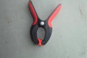
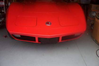
I am using four Craftsman spring clamps to hold the cover in place to see how it will fit before drilling the holes for the mounting hardware.
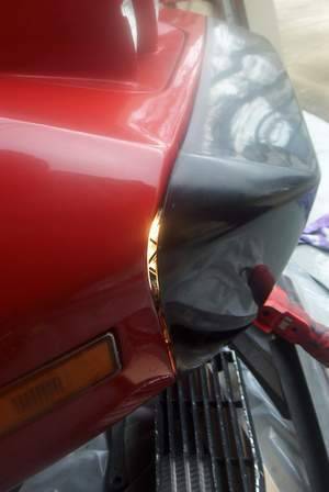
The passenger side has a large gap. There is a small area that is holding the bumper out away from the mounting surface that will need to be removed. This may be from when the fender had been replaced in the past. The urethane bumper is more flexible and may have pulled in tighter then the fiberglass bumper would. The driver side looks to fit nice.
There is a large gap because the top edge of the fender is holding the part away from the rest of the car.
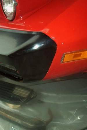
The drivers� side fits nicely against the car.
The gaps are not perfect but after removing material off both the fender and the back of the bumper the gaps are closed up. Now it is time to drill the holes for the mounting hardware. Once that is done I will finish fitting them together. It looks like I need to take more material off the car. Because I am not ready to repaint the car, I will leave it as is for now.
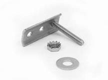
Here are the four pieces of mounting hardware removed from the old bumper. The bottom is the large part with the nuts welded on it. The piece on the right is the replacement 18-piece set sold for mounting the fiberglass bumper.
If
you were wondering if the original hardware could be used with the
fiberglass bumper, the answer is not without cutting it up. The urethane
bumper can be flexed enough to get the top and side pieces to fit in
place. Even though I am using the flexible fiberglass cover, it will not
bend enough for that.
I
have the new bumper fitted and bolted in place.
Now
it is off to the paint shop. Meantime, I have time to put the steel
bumper reinforcement back on and clean up the grilles. I will wait until
the bumper is bolted in place before I put the grilles back on. While I
have the grilles off, I used a wire wheel in my air grinder to clean
them up and repaint them. The grilles are used on 73 and 74 with the
only difference being that the 73�s grilles had chrome edges and the
74�s were just black.
Block sanding the surface with 500 grit dry sandpaper and finish off
scuffing the part with a Scotch-brite pad. Then seal it and repeat.
I
mounted the bumper back on the car along with the grilles and license
plate bracket.
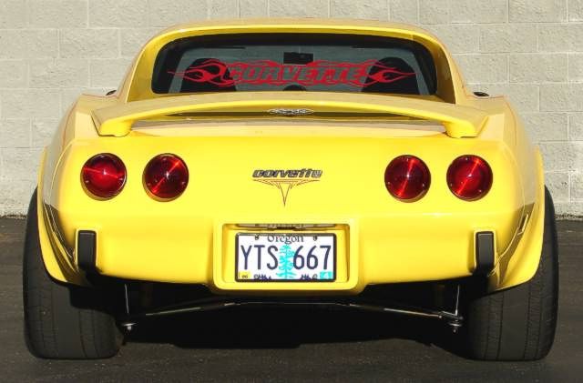
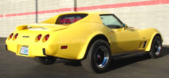
Once
everything fit nice I polished and waxed the car and it looks like new.
I have recovered 4 sets of seat over the years and
had had it with the hog rings. I tried one seat using strong tie wraps (
zip ties ) instead of the hog rings wherever the hog rings were used.
Pulling the tie wrap through the same area the hog ring would go and then
leaving them slightly loose but � connected� When you get the rest of the
seat done, all with tie wraps, you then snug the tie wraps to get a nice
tight fit where you want it. Then snug all the ties and snip off the loose
ends. I did my first set that way about 5 years ago and they hold just fine.
It goes nice and easy, hold fine and you can really adjust the fit of the
seat covers.
Back to Top
On every car I buy new or used I take off
one lug nut at a time & put ANTI-SEIZE LUBRICANT (some of this stuff will
handle 2000 degrees F) on the threads then re- torque to specs. You will
never have problems with lug nuts again. Also use it on spark plugs and it
really helps with aluminum heads. Use it on any nut or bolt you plan
on removing in the future.
Installing the Distributor
After using
the timing marks on the front engine pulley to bring #1 piston to
top-dead-center, when re-setting the distributor back in on a 350 Chevy
motor, a very handy little trick is to look down into the hole where the
distributor shaft goes and with a long screw driver, turn the slot in the
bottom directly towards the number one cylinder/plug and set
your distributor the same. It will either be exactly 180 degrees off
or it will be almost dead on the timing mark when you fire the engine back
up. If it just turns over and never fires up, take the distributor back out
and turn it 180 degrees and reset the distributor and it should fire up with
almost no re-adjusting of the timing. You will be very, very, close and a
big time saver.
If you have a
manual shift corvette C-2 or C-3 keep a hitch pin in your car somewhere.
I was out driving one day and the �j� clip on the clutch linkage
disintegrated, I used the hitch pin as an emergency repair and slid it on
from the top down indexed along the clutch pedal arm to hold all the linkage
together and not damage any of the wiring, this proved to be a great and
very easy fix in case of emergency
.
Back to Top
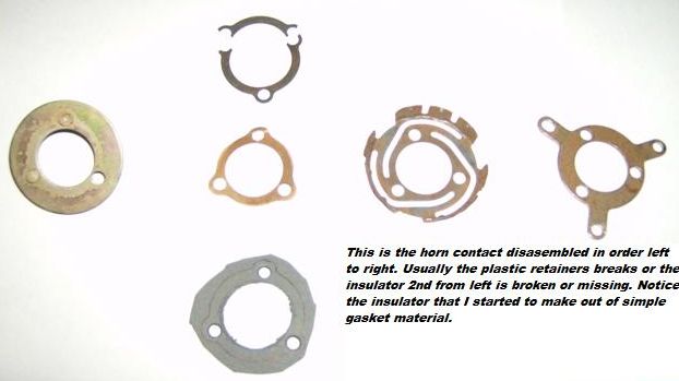
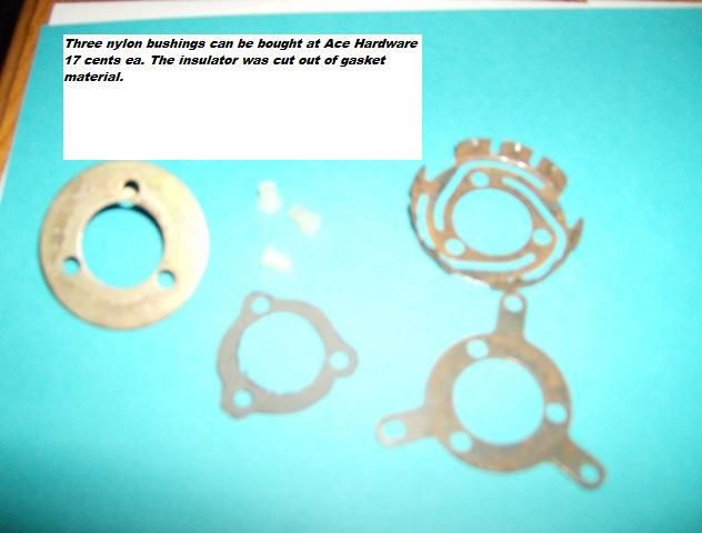
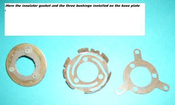
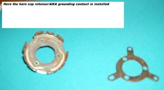
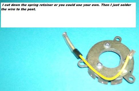
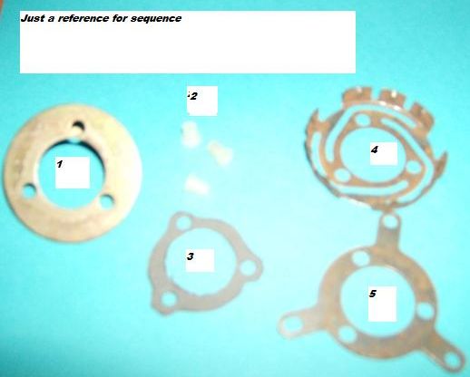
Horn Retainer FixHere is my tip for fixing the horn
retainer by eliminating the horn contact post and replacing it with a
spring and wire. Yes, it is only a $20.00 item but any place
you can save and fix it your self is a good thing. The horn cap retainer is
a weak design, held together with plastic rivets. The key to this repair is
the plastic bushings that can be found at any Ace Hardware store. I made a new
insulator gasket out of plain gasket material as the old insulator usually is
broken or missing. I guess the temperature spikes has a lot to do with it
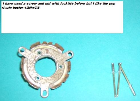
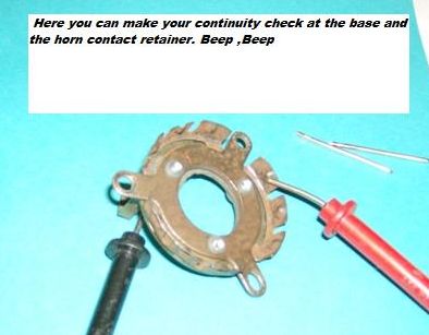
coming apart. I have used screws and nuts with locktite to hold it
all together but have found pop rivets to be a lot cleaner. I have also
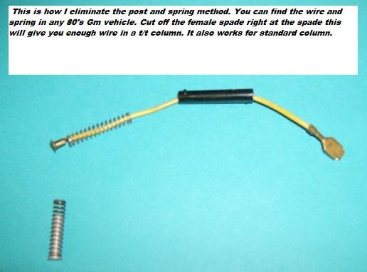
eliminated the post and spring with a wire and spring. The pictures
below will hopefully help with your repair.
Back to Top
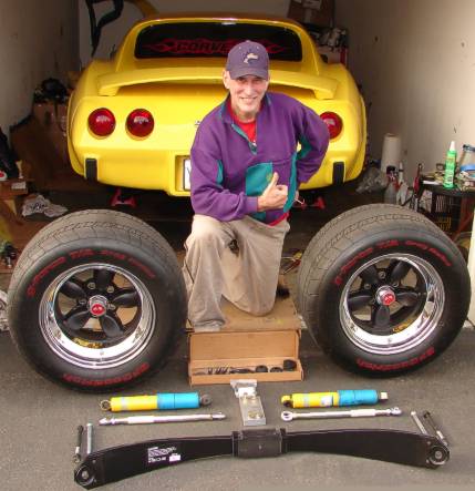
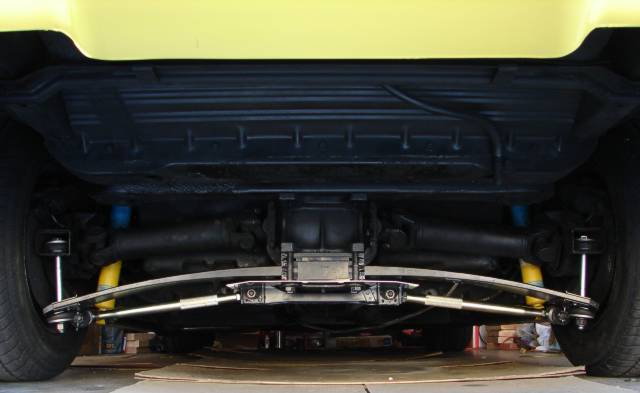
TRW spring, Bilstein shock, adjustable strut installation
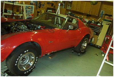
NOTE: This
whole job took me about 7 hours to do. If you follow the instructions I've
laid out, it will save you about three hours of work time, providing it is your
first time to attempt this. I've learned several shortcuts and things NOT
to do by trial and error. Should only take 3-4 hours now. Bear in mind
that in addition to what I did, since most have the rear exhaust and tire cover,
the exhaust will have to be dropped and tire tub and tire removed. I have
the hooker side-pipes and my tire cover assembly has been long removed.
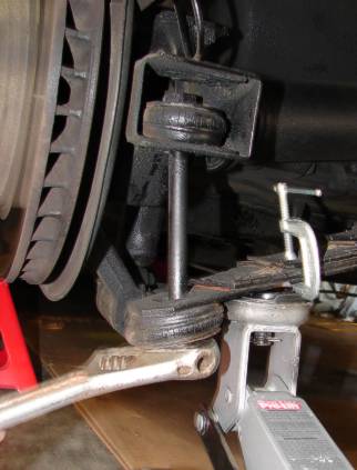
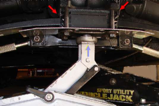
First, I jacked up the Vette and put the jack stands a few inches behind the
door frame on both sides. I then took off both rear tires. I placed
the jack under the spring bolt to relieve the tension. I then C-clamped
the spring so the jack wouldn't slip while I loosened the spring bolt.
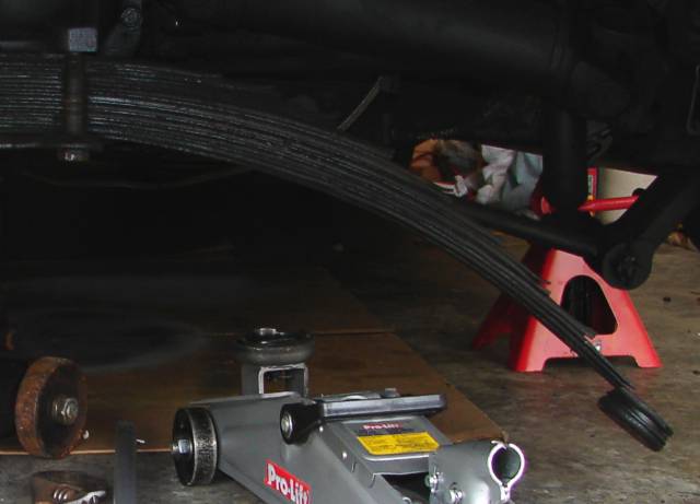
Here is what it looks like after I took the spring bolt out.
Quite a drop.
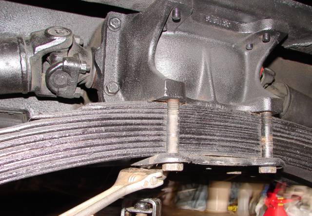
Next, I loosened the 4
big bolts holding the spring to the rear end.
The Spring is out! It
is heavy too!
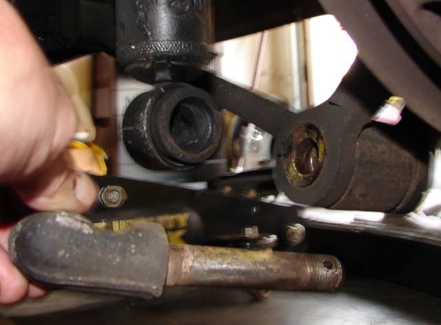
Okay, now it was time
to remove the L-shape bolt holding both the shock and strut.
After loosening that
bolt, I removed the top shock bolt in order to remove the bottom L-shaped bolt
holding the shock/strut.
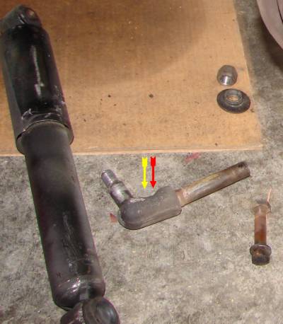
Here is what that
L-shape bolt looks like that holds the shock & strut.
Next I went over and
removed the bolt holding the strut to the strut bracket.
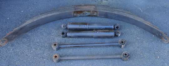
Yay! I am now halfway
as I got the spring, shocks and struts off.
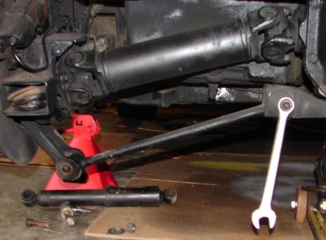
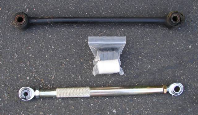
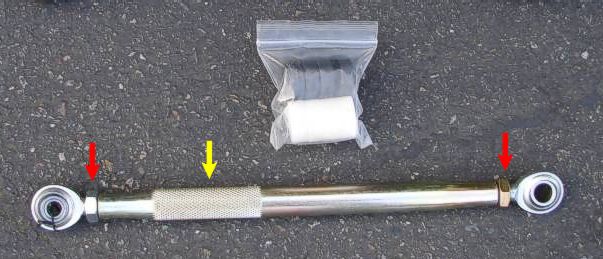
Big difference between
the stock strut and adjustable strut.
It took me about three
hours to remove the parts that I am replacing. Next on installing the new TRW
spring, Bilstein shocks & adjustable struts.
I installed the Bilstein shocks at the top first, then at the bottom. As
you can see by the picture, I installed the bottom of the shock first before
putting the L shape bolt through the strut bracket.
MISTAKE! It took me well over an hour to do that. On the other
side, I installed the strut bolt in first, then put the shock on, barely. This
only took an half hour.
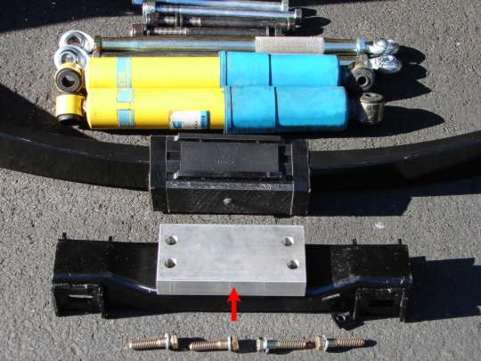
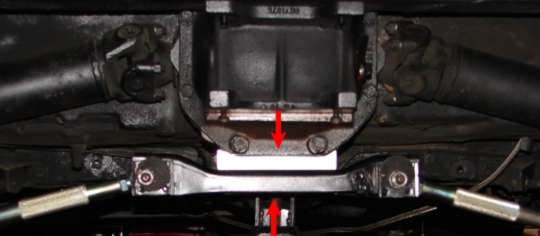
Next I installed the aluminum
spacer that goes between the strut bracket and differential, (RED
arrows).
The cam bolt is
suppose to be set at 6 o'clock. The left is correct, but I have to set the
drivers side.
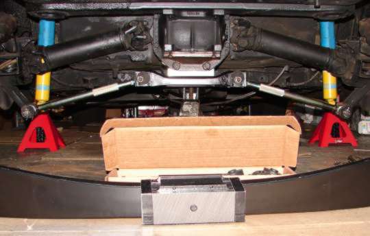
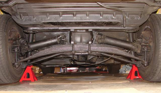
Here is what it looks
like so far... with TRW spring on the ground waiting to be put in.
Okay, wrap-up time...
(with exception of having to get two 10" spring bolts to replace the 8" ones).
If you decide you need the 10" bolts, several Corvette vendors have them.
Unless your VERY strong, it helps to use a jack to hold the spring center in
place to start the 4 bolts. There is a heat-shield and cover plate that is
bolted with that.
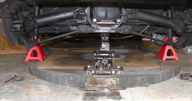
Next was to install
the spring bolts. These were tricky and I can save you about an hour of
time with the shortcut I learned. Only run the 4 bolts in the center (last
pix above) about halfway in so you can jiggle the outer spring a tad in order to
get the long spring bolt in the top AND the spring (two
red arrows). I tried it with the 4 center bolts all the way in and an
hour later still couldn't get that bolt in. I did the other side this way
and it only took 10 minutes! You also have to use a jack to move the
spring up in order to get the bolt through (bottom red
arrow). Be sure NOT to slip the jack off the metal tip or else you'll ruin
the spring!
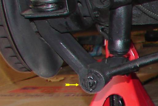
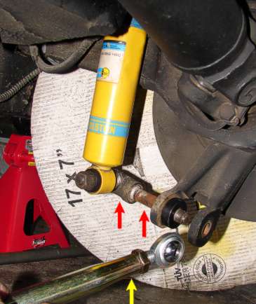
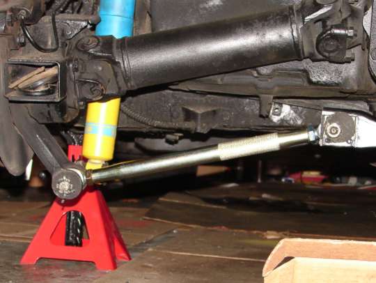
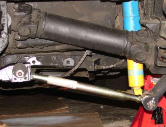
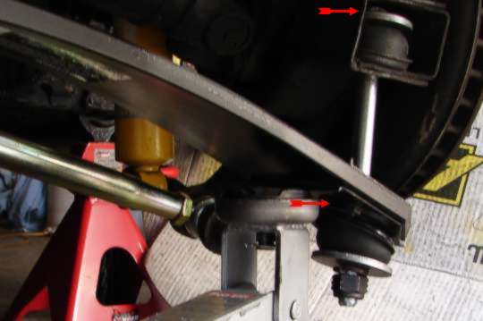
The struts are very
easy to adjust. Just use a level on the wheels and turn the two outer nuts
on the strut bar (red arrow) and twist the knurled part of bar (yellow
arrow) until you get the wheel/tire perpendicular.
and AFTER. Not bad,
not bad at all!
The TRW spring came
with a longer than stock bolts at 9" while others come with the 10" ones.
Boy was I wrong. When I measured the two bolts, the stock one was 7", TRW was
7-1/2" and the other one was 8". No good. I'm still at least 2" too
high (4.5" from fender-lip to top-tire). I'm going to get 10" bolts.
I will drive it around a bit and see if it settles some first.
NOTE: I did not get
the 10" bolts and decided to drive it awhile first. It did settle to the height
I wanted perfectly after a month of driving.
Although
I don't think anyone out there would need this tip by now, but if there is a new
C3 owner out there like me this could solve a fuel/performance issue with the
1981 L-81 engine. My car was shipped up to Canada by truck and while yes,
I did go stateside to view and drive it, I guess I just didn't drive it long
enough for the problem to present itself. The problem was this: While the
car was cold, it ran perfectly. However, after 45 minutes or so into the
ride, it would choke up, hesitate and it almost felt like a spark plug or spark
plug wire break down. The car would also start to shift gears (auto)
between first and second at the wrong times. Go around a corner, it would
drop to first when it didn't need to and then right away shift back up to second
with a slight clunk. The car was also burning a huge amount of fuel.
I was getting from a very full tank of gas about 45 miles to the first 1/4 mark
on the gas gauge.
A
recommended carburetor mechanic did the following: (Remember that this
carburetor has a primitive little computer control system designed to regulate
the air/fuel mixtures for minimum emissions and best performance.)
The fix was to first spray a full can of carburetor cleaner down the venturies
(not a pretty sight out the tail pipe)....then, into the shop where he THOUGHT
he'd have to pull the carburetor to punch out the two steel covers blocking you
from fooling around with the fuel/air mixture screws. I was lucky because
they were already out. He then advanced the timing between 13 and 15
degrees (NOT what GM specified at 7 or 8 degrees). He fiddled with his
meters and set the air/fuel mixture, fine tuned the timing, sprayed another can
of carburetor cleaner down until it flooded and stalled the engine. By
now, my fingernails were bleeding! He let the car sit for about a half
hour, replaced the stock air filter with a K&N, and took my car out for a drive.
When he returned, he said nothing but " you try it." The difference was
immediate as far as the shifting and performance was concerned. The
mileage reading would come with time and it did. Where I got about 45
miles to the first 1/4 tank mark on the fuel gauge, I am now getting between
70-80 miles to that same mark with the same driving habits. The car is
never driven hard so I don't know if what I'm getting now is even a good number
but I'm happier now then before for sure. I do know a few guys I ran into
this past summer had issues with the same thing and I passed this info to them
and feedback when I later saw them I got a 'thumbs up'. It seems that most
mechanics will set the timing to the spec's on the car's sticker and this is
where they go wrong. GM, I was told needed to get their emission numbers
way down for the state laws of the day and they more or less said to h*ll with
the fuel economy and performance. At least that's the way it was explained
to me. I hope this helps someone out there .
Back to Top
1.)
The rear bumpers and support brackets
2.)
License plate bezel and exhaust bezels
4.)
Ground strap from antenna
5.)
Gas tank ground and sending unit wire
1.)
Valence panel and air dam
2.)
Unbolt nose support from frame (will stay with body)
4.)
Ground straps (more than one place)
5.)
Carbon can vacuum line
6.)
Oil pressure gage line from motor
7.)
Throttle cable from motor
9.)
Heater and A/C hoses from motor
10.)
Alternator wires and temperature sending unit wire
11.)
Radiator hose and transmission cooling lines (radiator should be removed
or it will stay with the body)
1.)
Parking brake cable and brackets from under seat area
2.)
Shifter cable and down shift wire (automatic) and speedometer cable
3.)
Battery ground strap from frame
5.)
Seats (to lessen the weight)
Remove Bumper Support Rods
Remove Bumper Adjustment Brackets
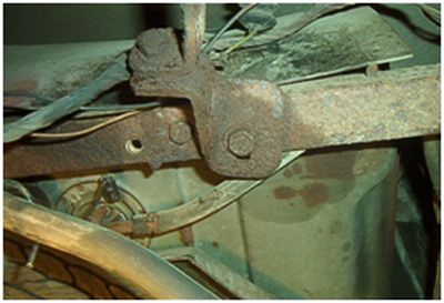
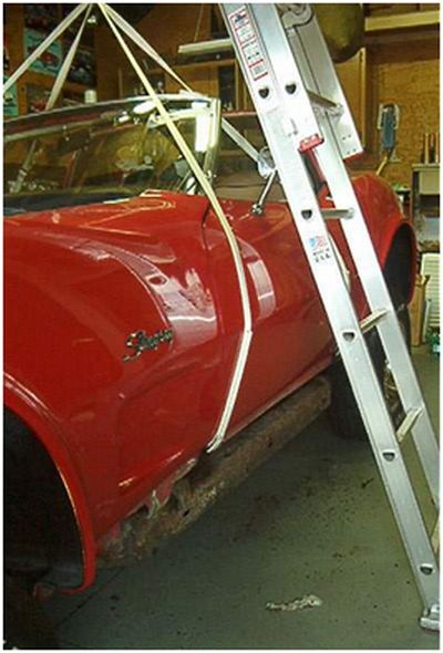
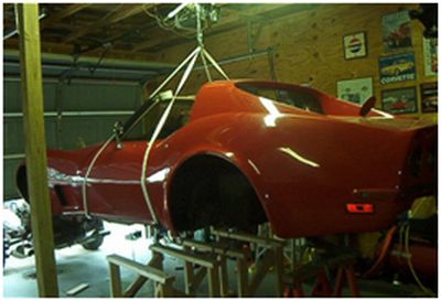
Attaching the lift straps - The straps have hooks that must catch the rocker
channels just in front of the doors and at the rear of the doors. Make
sure the rocker channels are not too rusty to hold up the weight. Support the
nose with a second come-a-long attached to the bumper beam.
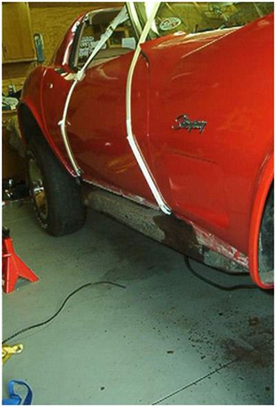
Slowly start lifting the body. Keep checking to make sure
everything is free from the frame.
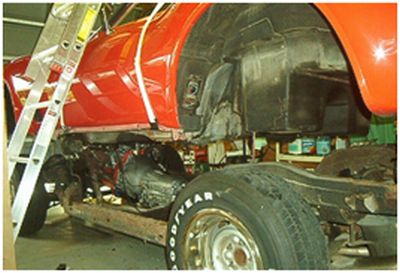
Lift the body enough to roll the chassis out from under it requires about 28
inches for the gas tank to clear.
Set the body down on something that will hold the weight and allow room to work
on it.
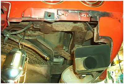
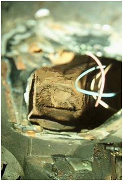
This is looking at the inside of the #3 mount once the access cover is removed.
This is the area where the #2 mount attaches under the windshield after the kick
panel is removed.
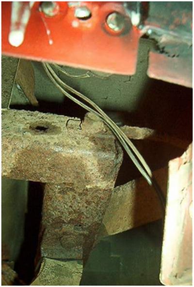
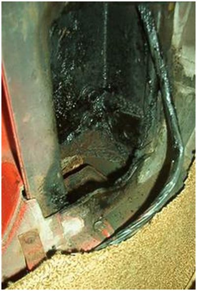
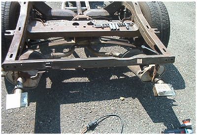
This is the �Bird Cage� that supports the body to the frame.
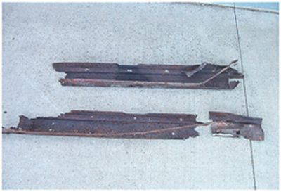
Here are the rotten rocker channels that support the body.
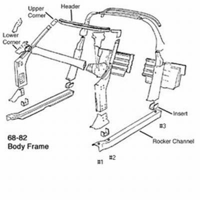
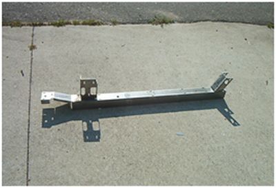
The replacement rocker channels and inserts need to be welded together.
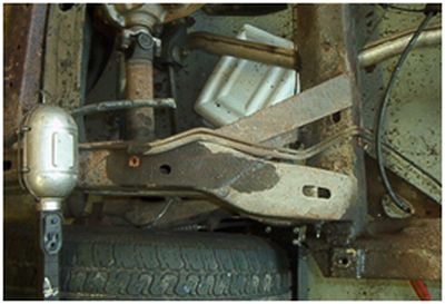
Check the frame for rot in front of the rear wheels.
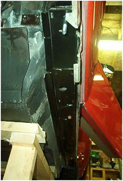
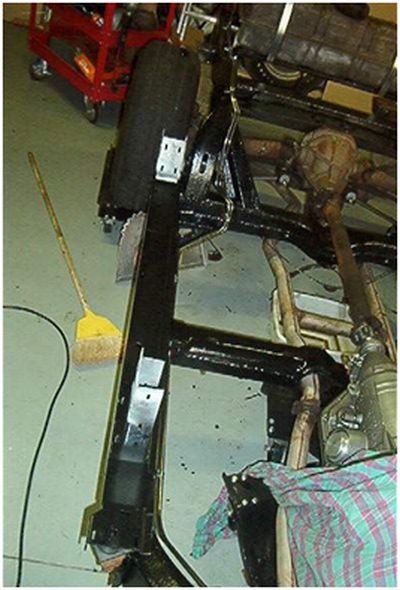
The new rocker channels are then fitted up inside the post and welded in place.
Remove the gas tank and check it for leaks. Then clean up the frame with a wire
wheel and power washer.
Chassis saver paint is applied and the stainless steel fuel and brake lines
installed.
The body is back on the frame where it belongs.